MSP430FR2355 Projects
Project Type: Embedded Systems
Project Members: Chris Ragland, Jacob Henson, Minh Nguyen, Polina Yefimenko
Published: 2023-08-21
Introduction
The projects described in this article are from a hardware elective offered at my university.
The class is an introduction to embedded systems. I enjoy learning about the low-level mechanics of how computers work. Even more, I enjoy building things that interact with the real world and the people that inhabit it.
The semester begins with us writing the projects in assembly. The first few are very simple, single file projects, and the code for them can reasonably be displayed within the article. However, at some point, moving to C in the middle of the semester the projects grow and snippets of code are provided instead of full files. To view the full source code for the project, check out my github.
Going forward in the article, each project begins with a description of the problem. Which is followed by the thoughts that went into implementing the project.Next, code snippets that describe how to implement the important features for that given project. Finally, a video that demonstrate the project in action.
Project 1: Assembly Language and Timer System
Problem Description
Produce an output in one of your LaunchPad LEDs when you press any of the push buttons on the LaunchPad.
Pseudo code
The simple solution to this problem was to implement a polling loop. Below I describe the actions necessary to meet the problem's requirements.
Setup:
  - Set P6DIR to output
  - Set P4/P2 DIR to be input
  - Enable pull up/down for both buttons
  - Set/select pull up for both buttons // active-low enable
  - Clear our LED1 (P1.0) // starts turned off
  - Remove high impedance

Main:
  - Check_is_pressed:
  - Test if button S1 is pressed
    - yes -> go to toggle
    - no  -> fall through
  - Test if button S2 is pressed
    - yes -> fall through
    - no  -> go to Check_is_pressed

Toggle:
 - toggle the bit in P6.6
 - Set R4 with very high value

Delay:
  - Decrement R4
  - Test if zero flag raised
    - yes -> fall through
    - no  -> jump to delay
  - Jump back to main // repeat loop forever
  - NOP // no operation
Code
init:
      bis.b #BIT6, &P6DIR 	  ; Set P6.6 as output
      mov.b #0, &P4DIR        ; Set P4.1 as input
      mov.b #0, &P2DIR        ; Set P2.3 as input

      bis.b #BIT3, &P2REN 	  ; Enable pull up/down for P2 button
      bis.b #BIT1, &P4REN 	  ; Enable pull up/down for P4 button
      bis.b #BIT3, &P2OUT 	  ; Select pull up for P2 button
      bis.b #BIT1, &P4OUT 	  ; Select pull up for P4 button

      bic.b #BIT6, &P6OUT 	  ; Clear P6OUT i.e., LED turned off on start

      bic.w #LOCKLPM5, &PM5CTL0   ; Disable GPIO high-impedance

main:
check_b1:
      bit.b #BIT3, &P2IN    ; Check button 1 (pull up) bit
      jz   	toggle_led      ; Jump to check again

      bit.b #BIT1, &P4IN    ; Check button 2 (pull up) bit
      jnz check_b1          ; Jump to check again

toggle_led:
      xor.b #BIT6, &P6OUT   ; Toggle LED light on button press

      mov.w #0FFFFh, R4     ; Store big value into accumulator

delay:
      dec.w R4              ; Decrement by 1 on each loop
      jnz   delay           ; Jump to delay while R4 > 0

      jmp main              ; Repeat forever

      nop                   ; Make the assembler happy
Project Video
Project 2: I/O and Timers (interrupts)
Project 2 was definitely more involved then the previous assignment. This project was our introduction to using interrupts within embedded devices.
Additionally, to reduce the number of ports used, instead of displaying the tens place and the ones place, we display one at a time.
We are constantly switching between which 7-segment screen we are displaying at any given time. However, it happens so fast that our human perception is not able to visibly notice the 7-segments repeatedly being turned on and off.
Problem Description
Produce an output showing the use of Digital I/O’s and TIMER_B. We need to build a counter from 00 to 59 in two seven-segment displays. The counter should operate as a 60 second / 1 minute timer. When it reaches 59, the counter should rollover and repeat the process.
Pseudocode
Before beginning the program, we calculate the time with the following equation.
- △t = T ⋅ N
- T = period
- N = count of overflows
The frequency of the timer ACLK=32.768kHz, which makes the period T=3.052⋅10^(-5) s
- N=2^15
- T⋅N = 3.052⋅10^(-5)⋅2^15 = 1s
Therefor we will use 2^15 as our initial value.
Now we can plan out our program with some simple english-like pseudocode.
Init:
      Set all the direction and output pins we will use
      Ensure they are initially turned off
      Disable high impedance
      Set up the timerB system
        > set initial value to 2^15
        > select ACLK and continuous
        > enable interrupt and clear flag
        > enable global interrupts
      Set desired binary for the segments into memory
      Set two pointers to point at memory and the values
      we put into them
main:
      Move the data for display one into our output ports
      Turn on display 0 and show the 10ths place
      Turn off display 0 and hide the 10ths place
      Move the data for display two into our output ports
      Turn on display 1 and show the ones place
      Turn off display 1 and hide the ones place
      Jump back to main and repeat
ISR_TIMERB_OVERFLOW:
      If Ones_pointer is at index 9:
        Ones_pointer = array.start
      Else:
        Ones_pointer++
      If Tenths_pointer is at index 6:
        Tenths_pointer = array.start
      Else:
        Tenths_pointer++
      Set initial value into TimerB register
      Clear the interrupt flag
      Return from interrupt
Now let's take a look at how we transferred out pseudocode into actual assembly instruction.
init:
;-- Set up output pins
      bis.b #BIT0, &P2DIR 		        ; Set P2.0 as output (SEG - A)
      bis.b #BIT1, &P2DIR 		        ; Set P2.1 as output (SEG - B)
      bis.b #BIT0, &P6DIR 		        ; Set P6.0 as output (SEG - C)
      bis.b #BIT1, &P6DIR 		        ; Set P6.1 as output (SEG - D)
      bis.b #BIT2, &P6DIR 		        ; Set P6.2 as output (SEG - E)
      bis.b #BIT3, &P6DIR 		        ; Set P6.3 as output (SEG - F)
      bis.b #BIT4, &P6DIR 		        ; Set P6.4 as output (SEG - G)

      bis.b #BIT0, &P3DIR 		        ; Set P3.0 as output (toggle LED0 10ths place)
      bis.b #BIT2, &P3DIR 		        ; Set P3.2 as output (toggle LED1 1s place)

      bic.b #BIT0, &P2OUT 		        ; P2.0 is set to low initially
      bic.b #BIT1, &P2OUT 		        ; P2.1 is set to low initially
      bic.b #BIT0, &P6OUT 		        ; P6.0 is set to low initially
      bic.b #BIT1, &P6OUT 		        ; P6.1 is set to low initially
      bic.b #BIT2, &P6OUT 		        ; P6.2 is set to low initially
      bic.b #BIT3, &P6OUT 		        ; P6.3 is set to low initially
      bic.b #BIT4, &P6OUT 		        ; P6.4 is set to low initially

      bis.b #BIT0, &P3OUT 		        ; Display 0 (tens place) initially turned off
      bis.b #BIT2, &P3OUT 		        ; Display 1 (ones place) initially turned off

      bic.b #LOCKLPM5, &PM5CTL0 	    ; Disable low power mode

;-- Set up timer0_B3
      bic.w #TBCLR, &TB0CTL           ; Clear Timer B and its dividers
      bis.w #8000h, &TB0R             ; Set initial value of TimerB (2^15)
      bis.w #TBSSEL__ACLK, &TB0CTL    ; Set clock source as ACLK
      bis.w #MC__CONTINUOUS, &TB0CTL  ; Set counting mode to continuous
      bis.w #TBIE, &TB0CTL            ; Enable TimerB interupt
      bic.w #TBIFG, &TB0CTL           ; Clear interrupt flag
      nop

      bis.w #GIE, SR                  ; Enable the global interupt
      nop

;-- Create pointers that will be used in loop
      mov.w #2000h, R4                ; R4 pointing at first position in array (10ths place)
      mov.w #2000h, R5                ; R5 pointing at first position in array (1's place)

;-- Main loop that will repeat forever
main:
      bic.w #0FFFFh, R6            ; R6 will be used as a mask register so we clear it
      mov.b @R4, R6                ; Move the binary data at the address in R4 into register R6
      and.b #00000011b, R6         ; Clear every bit except the first two
      bic.b #00000011b, &P2OUT     ; Clear the first two bits (A and B) from port 2
      bis.b R6, &P2OUT             ; Logical OR what is in R6 with P2 register
      mov.b @R4, R6                ; Move the binary data at the address in R4 into register R6
      and.b #01111100b, R6         ; Clear every bit in R6 except the ones we are using for P6
      rra.b R6                     ; We need to right shift because we start at bit0 in P6OUT
      rra.b R6                     ; Right shift one last time to get all the bits in right position
      bic.b #00011111b, &P6OUT     ; Clear all the bits we are using in P6OUT
      bis.b R6, &P6OUT             ; Logical OR the values inside of R6 with P6OUT

      bic.b #BIT0, &P3OUT          ; Turn on display zero (tenths place)
      bis.b #BIT0, &P3OUT          ; Turn off display zero

      bic.w #0FFFFh, R6            ; R6 will be used as a mask register so we clear it
      mov.b @R5, R6                ; Load value of 10ths place into R6
      and.b #00000011b, R6         ; Keep the first 2 bits
      bic.b #00000011b, &P2OUT     ; Clear the first two bits in P2.(0 and 1)
      bis.b R6, &P2OUT             ; BITWISE OR the two registers together
      mov.b @R5, R6                ; Move the value at the address stored in R5 into R6
      and.b #01111100b, R6         ; Get the remaining bits from @R4
      rra.b R6                     ; We need to right shift because we start at bit0 in P6OUT
      rra.b R6                     ; Right shift one last time to get all the bits in right position
      bic.b #00011111b, &P6OUT     ; Clear bits for output in P6OUT
      bis.b R6, &P6OUT             ; BITWISE OR the two registers together

      bic.b #BIT2, &P3OUT          ; Turn on display one (ones place)
      bis.b #BIT2, &P3OUT          ; Turn off display one

      jmp main                     ; Wait for interrupt

;----------------------------------------------
; Interrupt Service Routines
;----------------------------------------------

ISR_TIMER0_B3_OVERFLOW:
      cmp #2012h, R5                ; If R5 is at 9th index send to start of array
      jnz else_one                  ; R5 is not at 9th index go to else statement

;-- R5 is pointing at 9th index (if block)
      mov.w #2000h, R5              ; R5 pointing at first position in array (1's place)
      incd R4                       ; R5 carry into R4 increment by 1
      jmp end_else_one              ; Branch to the instruction after the first else

else_one:
      incd R5                       ; Increment the address in R5 by 2 (memory is in even blocks)

end_else_one:
      cmp #200ch, R4                ; If R4 is at 6th index send to start of array
      jnz else_two                  ; R4 is not at the 6th index, go to else statement

;-- R4 is poiting at 6th index (if block)
      mov.w #2000h, R4              ; R4 pointing at first position in array (10ths place)
else_two:
      bis.w #8000h, &TB0R           ; Set initial value of TimerB (2^15)
      bic.w #TBIFG, &TB0CTL         ; Lower flag raised for interrupt
      reti                          ; Return from interrupt
Wiring Diagram
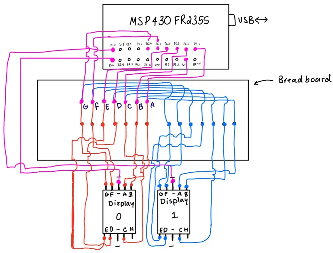
Project 2 Video
Project 3: Using The ADC (Analog Digital Converter)
Problem Description
Using the ADC System, produce a blinking output in one external LED on a bread board. The blinking frequency (hint: Time in between toggling) needs to be controlled using a potentiometer as an analog input.
Pseudocode
At this point in the course, I was feeling a lot more comfortable with thinking in assembly that my pseudocode could almost be directly transferred to assembly language.
init:	clear R4				//will hold ADC result
		clear any values in P4OUT
		set P4 to be output

		change the function purpose
		in register P5 to be analog

		disable low power mode

		/* set up timer B */
		Clear timer b and its dividers
		Set initial value to 2^15 in TB0CCR0
		Set ACLK
		Put TB0 into up mode 	//overflow will be TB0CCR0
		Enable timer b interrupts
		Clear timer b interrupt flag

		/* set up ADC */
		Clear initial sample hold time
		Set sample hold time to 16 cycles
		Turn on ADC
		Set signal source from timer
		Select SMCLK and single channel
		Clear initial 10-bit resolution
		Set resolution to 12 bits
		Set reference and input channel source
		Enable interrupt for ADC conversion completion

		Enable global interrupt

		Enable conversion and start conversion

Main: 	loop to main forever waiting for interrupts

ISR_conversion:
		Move data in ADC into R4
		Multiply by 4 so the time is visible
		To our eyes
		Put that value into TB0CCR0 //setting overflow
		Enable conversion and begin conversion
		Return from interrupt

ISR_timerB:
		Toggle LED on bread board
		Clear interrupt flag
		Return from interrupt
Code
init: CLR.w R4                      ; R4 will hold ADC result, clear
                                    ; any previous value
      CLR.w &P4OUT                  ; clear any value in P4.0
      mov.b #0FFh, &P4DIR           ; set P4.0 to be output

      bis.b #BIT0, &P5SEL0          ; set P5SEL0 = 1
      bis.b #BIT0, &P5SEL1          ; set P5SEL1 = 1

      bic.b #LOCKLPM5, &PM5CTL0     ; disable low power mode

 ; --- timer b set up

      bic.w #TBCLR, &TB0CTL         ; clear Timer B and its dividers
      mov.w #8000h, &TB0CCR0        ; set initial value of timerB in
                                    ; CCR0 (2^15)

      bis.w #TBSSEL__ACLK, &TB0CTL 	; set clock source as ACLK
      bis.w #MC__UP, &TB0CTL 		; set counting mode to continuous
      bis.w #TBIE, &TB0CTL          ; enable TimerB interrupt
      bic.w #TBIFG, &TB0CTL         ; clear interrupt flag
      nop

; --- configure ADC

      bic.b #ADCSHT, &ADCCTL0       ; clear initial sample hold time
      mov.w #0210h, &ADCCTL0        ; set sample hold time to 16-
                                    ; cycles and turn on ADC

      mov.w #0218h, &ADCCTL1        ; set signal source from timer
                                    ; select SMCLK and single
                                    ; channel

      bic.b #ADCRES, &ADCCTL2       ; clear initial 10-bit resolution
      mov.w #0020h, &ADCCTL2        ; set resolution to 12 bits
      mov.w #0008h, &ADCMCTL0       ; set reference and input channel
                                    ; source

      bis.w #ADCIE0, &ADCIE         ; enable interrupt enable
      nop

      bis.w #GIE, SR                ; enable the global interrupt
      nop

      mov.w #0213h, &ADCCTL0        ; enable conversion and begin
                                    ; conversion

main: jmp main                      ; loop to main waiting for interrupt
The main program is very simple, it sits in the main loop after the initial setup and waits for interrupts to happen. The entire application rests on the interrupts and what they do when called.
Below are the interrupt functions for this program.
ISR_conversion:
      mov.w ADCMEM0, R4       ; move data in ADC memory to
                              ; R4
      rlc.w R4                ; multiply by two. Slow down
                              ; frequency
      rlc.w R4                ; multiply by two. Slow down
                              ; frequency
      mov.w R4, &TB0CCR0      ; put the output of ADC into
                              ; TB0CCR0
      mov.w #0213h, &ADCCTL0  ; enable conversion and begin
                              ; conversion
      reti                    ; restore stack pointer and status
                              ; register
ISR_timerB:
      xor.b #BIT0,  &P4OUT    ; toggle led on breadboard
      bic.w #TBIFG, &TB0CTL   ; clear interrupt flag
      reti                    ; restore stack pointer and status
                              ; register
Wiring Diagram
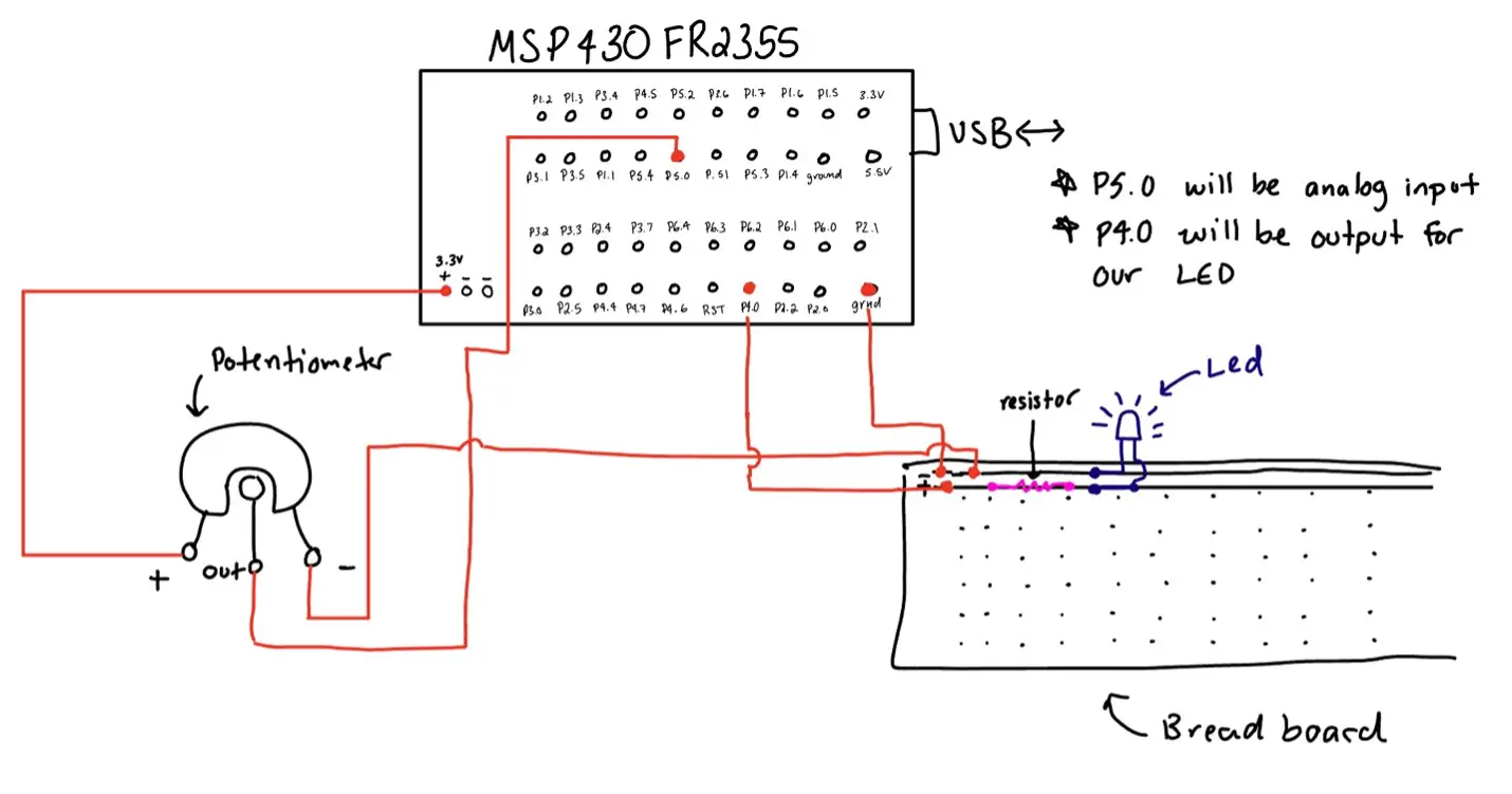
Project 3 Video
Project 4: Using 4x4 Matrix Keypad, I2C (Inter-Integrated Circuit) LCD, & PWM
Problem Description
Using the 4x4 matrix keypad, LCD screen, brush motor, and the MSP430FR2355 micro-controller, the task at hand is to control the pulse-width-modulation (PWM) via user input. The user must be able to enter a number into the keypad, pressing enter and causing the number to display on the LCD screen. The MCU communicates to the LCD screen with the on-board I2C communication module. This number is then used to set the duty-cycle of the motor.
Pseudocode
At this point in the class, we have finally switched over to learning embedded C. Assembly is great but C is just so fun and natural in the way we write programs.
Due to the project including several header files and source files I will only post the main file and the keypad file that describes the program for the most part. This goes for the Pseudocode and the actual code.
Main
/* main */

Setup timerB0.
Setup keypad.
Initialize I2C communication.

Setup P2.0 to be the pin that sends the on signal to the motor.
Setup P2.1 to be the pin that sets the direction of the motor spin.

Take MCU out of low-power mode
Enable global interrupts

Setup LCD screen
Set initial message to be: “Duty Cycle: 0 %”

While(1)
{
	While (wait for user to finish input)
      {
	      /* spin until user presses enter */
      }

      For (small delay loop) {}

      If entered value < 100:
	      TB0CCR1 = new value from user
	      Ensure that the interrupt for ccr1 is enabled
	      Write the new duty cycle to the LCD screen
      Else:
	      Disable interrupt for CCR0 so motor does not turn off
	      No matter the value entered set LCD to 100%
      Reset variables (entered_value, is_complete, digit_count) to 0 for a new value to be entered by the user.
}
Keypad
/* keypad.c */

Void setup_keypad(void)
{
      Set pin directions for p1.0 – p1.3 are output, p1.4 – p1.7 are input.
      Enable resistors for pins.
      Enable pull up resistors for p1 pins.

      Enable interrupts for all column pins.
      Set edge sensitivity to HIGH to LOW.
      Lower flags for interrupts.
}

//interrupts
#pragma vector = PORT1_VECTOR
__interrupt void ISR_KEYPRESS(void)
{
      Scan the keyboard testing which button was pressed.
      Use this value to find its key in the 4x4matrix.

      If key == ‘A’ and user has not pressed enter yet:
            is_complete = 1
      Else if key is a digit:
            Add the entered value to the end of the already present value.
      FORMULA: value = (value * 10) + key

      Reset p1 pins for the columns and rows
      Lower all flags up for p1
}
These two files perform most of the work. Setting up the project and handling the user input into the keypad. The timer is responsible for turning the LED on and off. While the LCD code is responsible for displaying the current PWM Duty Cycle. Again, if you wish to see the full code check out my github.
Code
/* main.c */

#include <msp430.h>
#include "./src/lcd/LiquidCrystal_I2C.h"
#include "./src/keypad/keypad.h"
#include "./src/timer/timer.h"

int main(void)
{
    WDTCTL = WDTPW | WDTHOLD;   // stop watch dog timer

    /* setup project */
    timer_b0_setup();           // configure timer B0 for PWM
    setup_keypad();             // configure keypad and pins
    I2C_Init(0x27);             // configure MCU i2c

    /* P2.0 used for PWM signal to motor */
    P2DIR |= BIT0;
    P2OUT |= ~BIT0;

    /* P2.1 used for motor direction */
    P2DIR |= BIT1;
    P2DIR |= BIT1;

    PM5CTL0 &= ~LOCKLPM5;        // Turn on GPIO
    __enable_interrupt();

    LCD_Setup();                // set up LCD screen
    LCD_SetCursor(0, 0);        // set initial cursor to start of screen
    LCD_Write("Duty Cycle: 0 %");
    int i;

    while(1)
    {
        /* wait for user to send input value */
        while(is_complete == 0)
        {
            /*
             * wait for user to input values and press 'A'
             * on the keypad
             */
        }
        for(i=0;i<10000;i++){}      // small delay to allow values to enter

        /* if value is less then 100 it will not cause an overflow */
        if (entered_value < 100)
        {
            TB0CCR1 = (entered_value * PERIOD) / 100;
            TB0CCTL1 |= CCIE;
            LCD_ClearDisplay();
            LCD_Write("Duty Cycle: ");
            LCD_WriteNum(entered_value);
            LCD_SetCursor(14,0);
            LCD_Write("%");
        }
        /* otherwise just turn off the interrupt and let motor run */
        else
        {
            TB0CCTL1 &= ~CCIE;             // turn off interrupts
            LCD_ClearDisplay();            // clear display
            LCD_Write("Duty Cycle:100%");  // set value to 100% as max
        }

        /* reset variables for a new value to be entered */
        entered_value = 0;
        is_complete = 0;
        digit_count = 0;

    }
}
/* keypad.c and keypad.h */
#ifndef __KEYPAD_H_
#define __KEYPAD_H_
#include <msp430.h>
#define KEYPORT P1OUT //keypad port used
#define MAX_DIGITS 3 //max digit count for keypad
/* define columns */
#define COL1 (0x10 & P1IN)
#define COL2 (0x20 & P1IN)
#define COL3 (0x40 & P1IN)
#define COL4 (0x80 & P1IN)
extern unsigned int key_value[4][4];
extern unsigned int entered_value; //key pressed on keypad
extern unsigned int digit_count; //keys pressed count
extern unsigned int is_complete; //finished entering numbers
extern unsigned int key;
/* function prototypes */
void setup_keypad(void);
#endif //__KEYPAD_H_
#include "keypad.h"
#include "../timer/timer.h"
#include "../lcd/LiquidCrystal_I2C.h"
extern unsigned int entered_value = 0; //key pressed on keypad
extern unsigned int digit_count = 0; //keys pressed count
extern unsigned int is_complete = 0; //finished entering numbers
extern unsigned int key = 0;
extern unsigned int key_value[4][4] = {{'1', '2', '3', 'A'},
{'4', '5', '6', 'B'},
{'7', '8', '9', 'C'},
{'*', '0', '#', 'D'}};
void setup_keypad(void)
{
P1DIR = 0x0F; //P1.4 - P1.7 set to input, P1.0 - P1.3 set to output
P1REN = 0xFF; //enable resistor for P1.4 - P1.7 pins
P1OUT = 0xF0; //P1.4-P1.7 pull-up resistor, P1.0-P1.3 initially off
P1IE |= BIT4; //col1 interrupt enable
P1IE |= BIT5; //col2 interrupt enable
P1IE |= BIT6; //col3 interrupt enable
P1IE |= BIT7; //col4 interrupt enable
P1IES |= BIT4; //edge sensitivity HIGH - LOW
P1IES |= BIT5; //edge sensitivity HIGH - LOW
P1IES |= BIT6; //edge sensitivity HIGH - LOW
P1IES |= BIT7; //edge sensitivity HIGH - LOW
P1IFG &= ~BIT4; //lower flag for row
P1IFG &= ~BIT5; //lower flag for column
P1IFG &= ~BIT6; //lower flag for column
P1IFG &= ~BIT7; //lower flag for column
}
/* interrupts */
#pragma vector = PORT1_VECTOR
__interrupt void ISR_KEYPRESS(void)
{
/* scan for the key */
unsigned int row, col;
for (row = 0; row < 4; ++row)
{
KEYPORT = ((0x01 << row) ^ 0xFF); // send each row to zero
if(!COL1)
{
while(!COL1); // spin while button is pressed
col = 0;
break;
}
if(!COL2)
{
while(!COL2);
col = 1;
break;
}
if(!COL3)
{
while(!COL3);
col = 2;
break;
}
if(!COL4)
{
while(!COL4);
col = 3;
break;
}
KEYPORT |= (0x01<<row);
}
key = key_value[row][col]; // set key = key_pressed
/* set value for percentage */
if (digit_count < MAX_DIGITS)
{
if (key == 'A' && is_complete == 0) // number finished
{
is_complete = 1;
}
else if ((key >= '0' && key <= '9'))
{
/* shift current value to add next number */
entered_value = (entered_value * 10) + (key - '0');
++digit_count;
}
}
else
{
is_complete = 1;
}
P1OUT = 0xF0; //reset P1 pins for columns and rows
P1IFG = 0x00; //lower flags
}The keypad is a pretty hefty file as it requires a lot of setup. The program itself for detecting which key is pressed is a tad bit more complicated as we use a technique that allows us to reduce from 16 wires (1 for each key) down to 8 wires (4 for the rows and 4 for the columns).
For a more detailed explanation of the code, watch the video for the project where I explain what is happening.
Wiring Diagram
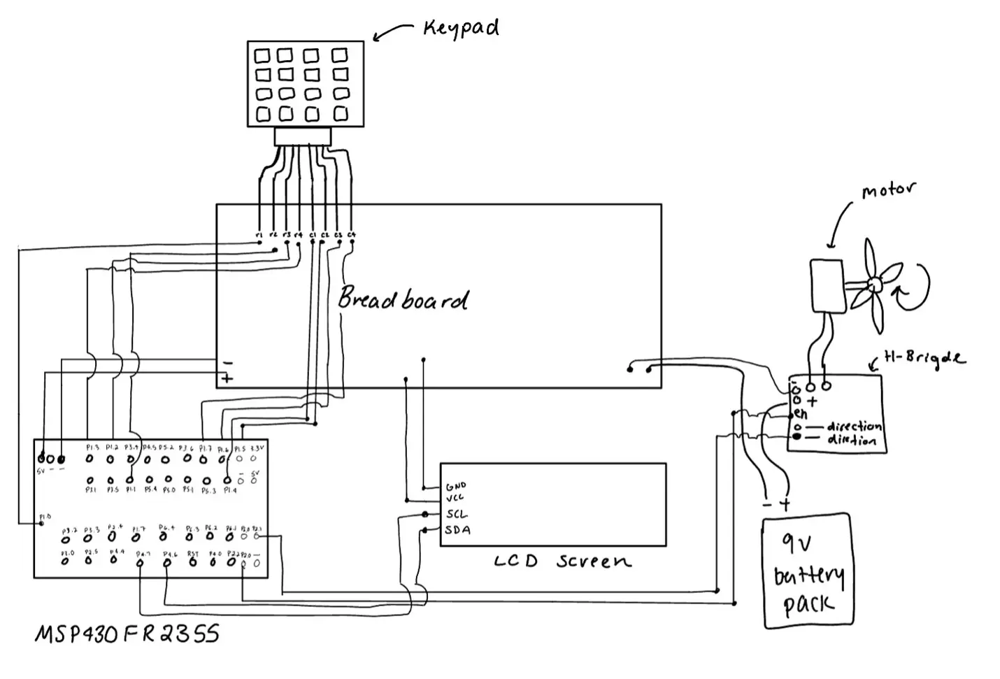
Project 4 Video
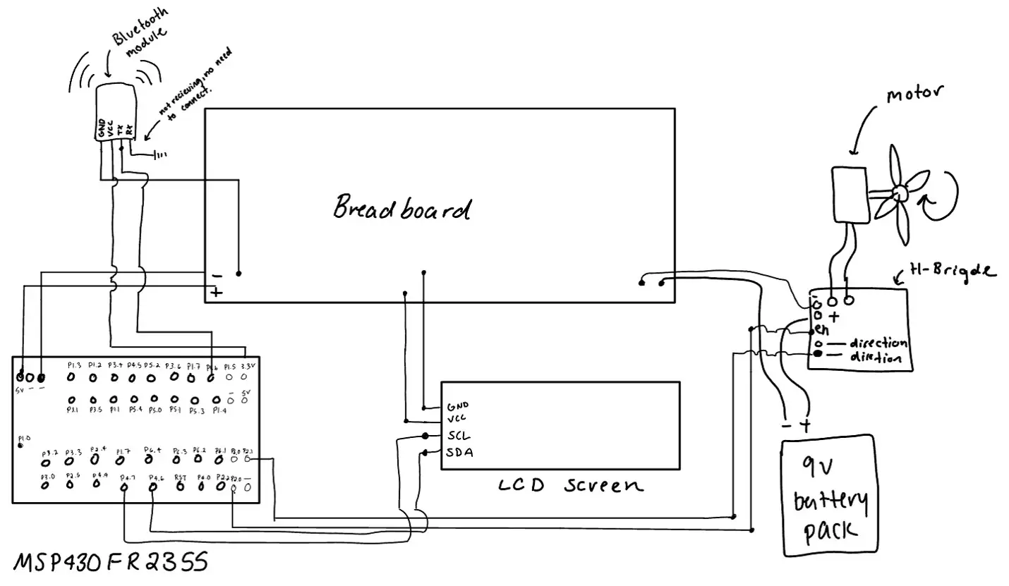
Final Project: Bluetooth with UART, I2C (Inter-Integrated Circuit) LCD, & PWM
Problem Description
Using the H10 Bluetooth module, LCD screen, brush motor, and the MSP430FR2355 micro-controller, the task at hand is to control the pulse-width-modulation (PWM) via user input. The user must be able to connect to the bluetooth module and via mobile application, input a numerical value, and send that value through microwave frequencies to the H10 Bluetooth device. When the user presses submit in the application, the values are transferred via UART to the MSP430FR2355 on-board UART receiver pin. The MCU communicates this value to the LCD screen with the on-board I2C communication module. This number should then be used to set the duty-cycle of the motor.
Pseudocode
Similar to project 4, I will only display the main files that make the magic happen. For this project those are the main, timer, and bluetooth module files. I will only include the main pseudocode because the code portion is rather large and more important then the pseudocode taking up space.
main
/* main.c */
Setup timerB0.
Setup Bluetooth.
Initialize I2C communication.

Setup P2.0 to be the pin that sends the on signal to the motor.
Setup P2.1 to be the pin that sets the direction of the motor spin.

Take MCU out of low-power mode
Enable global interrupts

Setup LCD screen
Set initial message to be: “Duty Cycle: 0 %”

While(1)
{
	While (wait for user to finish input)
      {
	      /* spin until user presses enter */
      }

      For (small delay loop) {}

      If entered value < 100:
	      TB0CCR1 = new value from user
	      Ensure that the interrupt for ccr1 is enabled
	      Write the new duty cycle to the LCD screen
      Else:
	      Disable interrupt for CCR0 so motor does not turn off
      No matter the value entered set LCD to 100%
      Reset variables (entered_value, is_complete, digit_count)
      to 0 for a new value to be entered by the user.
}
Code
Let's now look at the code that made the magic happen.
/* main.c */
#include <msp430.h>
#include "./src/lcd/LiquidCrystal_I2C.h"
#include "./src/timer/timer.h"
#include "./src/bluetooth/bluetooth.h"

int main(void)
{
	WDTCTL = WDTPW | WDTHOLD;	  // stop watch dog timer

	/* initial setup */
	timer_b0_setup();
	timer_b1_setup();
	bluetooth_init();
    	I2C_Init(0x27);                 // configure MCU i2c

    	/* P2.0 will be PWM output */
	P2DIR |= BIT0;
	P2OUT &= ~BIT0;

   	/* set motor direction */
    	P2DIR |= BIT1;
    	P2OUT |= BIT1;

	PM5CTL0 &= ~LOCKLPM5;           // turn off high impedance
	__enable_interrupt();           // global enable

    	LCD_Setup();                    // set up LCD screen
    	LCD_SetCursor(0, 0);            // set initial cursor to start of screen
    	LCD_Write("Duty Cycle: 0 %");   // initial message on LCD screen

	while (1)
	{
	    /* wait for user to send input value */
	    while(is_complete == 0)
	    {
	        /*
	         * wait for user to input values which will
	         * trigger timerB1 to start counting.
	         * Once it overflows is_complete will be set to 1 (true)
	         */
	    }
	    int i;
	    for(i=0;i<10000;i++){}      // small delay to allow values to enter

	    /* if value is less then 100 it will not cause an overflow */
        if (entered_value < 100)
        {
            TB0CCTL1 |= CCIE;       // enable CCR1 interrupt
            TB0CCR1 = (entered_value * PERIOD) / 100;
            LCD_ClearDisplay();
            LCD_Write("Duty Cycle:");
            LCD_WriteNum(entered_value);
            LCD_SetCursor(14,0);
            LCD_Write("%");
        }
        /* otherwise set the value to period - 1 = 655 */
        else
        {
            TB0CCTL1 &= ~CCIE;             // enable CCR1 interrupt
            LCD_ClearDisplay();            // clear display
            LCD_Write("Duty Cycle:100%");  // set value to 100% as max
        }
        TB1CCTL0 &= ~CCIE;                 // disable TB1 from interrupting again
        TB1CCTL0 &= ~CCIFG;                // lower flag
        entered_value = 0;                 // reset for a new value
        is_complete = 0;                   // reset for new entry
	}
}
/* timer.c and timer.h */
#ifndef __TIMER_H_
#define __TIMER_H_
#define PERIOD 655 // period of PWM
/* function prototypes */
void timer_b0_setup(void);
void timer_b1_setup(void);
#endif /* __TIMER_H_ */
#include <msp430.h>
#include "timer.h"
#include "../bluetooth/bluetooth.h"
#include "../lcd/LiquidCrystal_I2C.h"
void timer_b0_setup(void)
{
/* setup timer */
TB0CTL |= TBCLR; // clear clock
TB0CTL |= MC__UP; // up mode
TB0CTL |= TBSSEL__ACLK; // select A clock
/* initial on-time and period */
TB0CCR0 = PERIOD; // period length for LED
TB0CCR1 = 0; // 0% duty cycle initial
/* interrupts */
TB0CCTL0 |= CCIE; // enable CCR0 interrupt
TB0CCTL1 |= CCIE; // enable CCR1 interrupt
TB0CCTL0 &= ~CCIFG; // lower flag
TB0CCTL1 &= ~CCIFG; // lower flag
}
void timer_b1_setup(void)
{
/* setup timer */
TB1CTL |= TBCLR; // clear clock
TB1CTL |= MC__UP; // up mode
TB1CTL |= TBSSEL__ACLK; // select A clock
TB1R = 0; // ensure TB1R is set to 0
TB1CCR0 = 3500; // flag at 3500 overflows
}
/* ISR DEFINTIONS */
#pragma vector = TIMER0_B0_VECTOR
__interrupt void ISR_TB0_CCR0(void)
{
/* turn led/motor on if not at zero */
if (TB0CCR1 != 0)
{
P2OUT |= BIT0;
}
TB0CCTL0 &= ~CCIFG; // lower flag
}
#pragma vector = TIMER0_B1_VECTOR
__interrupt void ISR_TB0_CCR1(void)
{
P2OUT &= ~BIT0; // turn led/motor off
TB0CCTL1 &= ~CCIFG; // lower flag
}
#pragma vector = TIMER1_B0_VECTOR
__interrupt void ISR_TB1_CCR0(void)
{
is_complete = 1; // mark input from user complete
}/* bluetooth.c and bluetooth.h */
#ifndef __BLUETOOTH_H_
#define __BLUETOOTH_H_
extern unsigned int entered_value;
extern unsigned int is_complete;
void bluetooth_init(void);
#endif //__BLUETOOTH_H_
#include <msp430.h>
#include "bluetooth.h"
extern unsigned int entered_value = 0;
extern unsigned int is_complete = 0;
void bluetooth_init(void)
{
/* set up UART */
UCA0CTLW0 |= UCSWRST; // software reset
UCA0CTLW0 |= UCSSEL__ACLK; // select ACLOCK (32.768kh)
UCA0BRW = 3; // divider = 3
UCA0MCTLW = 0x9200; // modulation
P1SEL1 &= ~BIT6; // set up RX mode
P1SEL0 |= BIT6;
UCA0CTLW0 &= ~UCSWRST; // take out of software reset
UCA0IE |= UCRXIE; // interrupt enable
}
#pragma vector = EUSCI_A0_VECTOR
__interrupt void ISR_A0_RX(void)
{
unsigned int value = UCA0RXBUF;
/* if entered value is a digit, then process it */
if (value >= '0' && value <= '9')
{
entered_value = (entered_value * 10) + (value - '0');
TB1CCTL0 |= CCIE; // enable TB1 interrupts, ie: start timer
}
TB1R = 1; // restart timer
}Wiring Diagram